In-depth Analysis of the Working Principle of Piston Pumps: From Structure to the Core Logic of Reciprocating Conveyance
创始人
2025-09-16 10:55:09
0

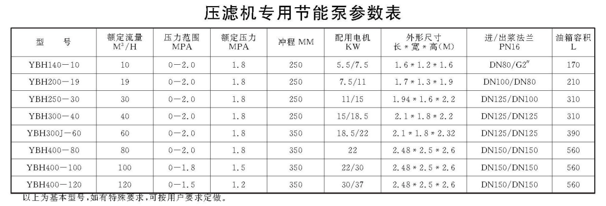
压滤机专用节能泵参数

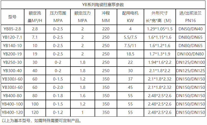
YB普通泵系列陶瓷柱塞泵参数

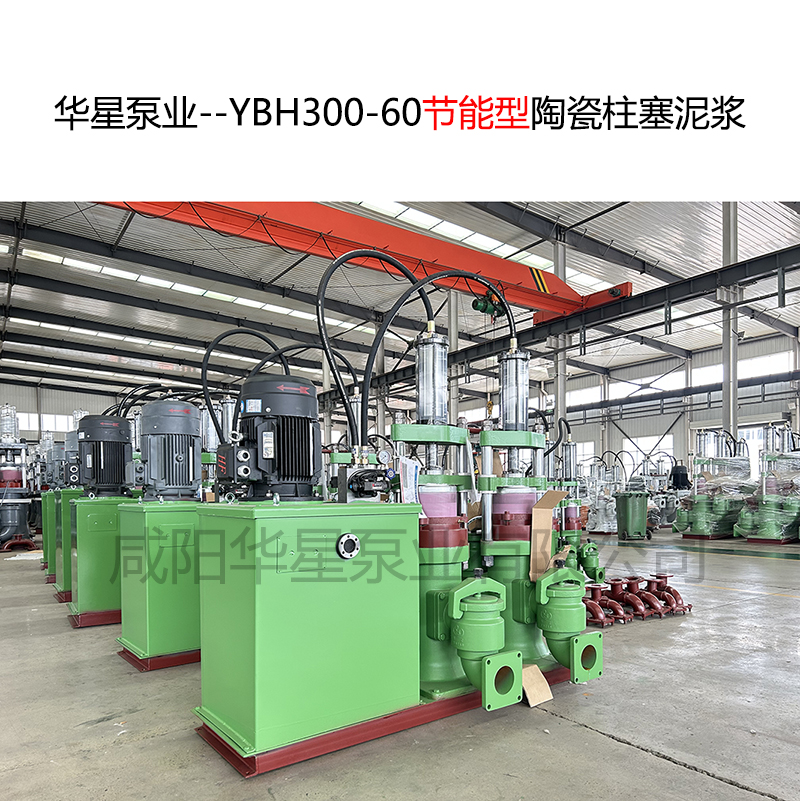
YBH300-60

I. Core Structure of Piston Pumps: The "Hardware Foundation" for Reciprocating Conveyance

The operating logic of a piston pump relies on a closed loop of "power drive - volume change - material conveyance". Its core structure can be divided into three major modules: the power transmission system, the volume change system, and the one-way control assembly. All components work in synergy to achieve the stable output of pressure and flow.

  1. Power Transmission System: The "Power Source" for Driving Reciprocating Motion

The core function of the power transmission system is to convert the rotational motion of the motor into the linear reciprocating motion of the plunger, which is the prerequisite for achieving volume change. It mainly includes the following components:
Motor and reduction gearbox: Industrial-grade piston pumps mostly use three-phase asynchronous motors. The reduction gearbox converts high rotational speed (usually 1450r/min) to low rotational speed (50-200r/min), reducing the plunger movement speed and avoiding increased wear and pressure fluctuations caused by high-speed reciprocation.

Crankshaft/cam mechanism: The output shaft of the reduction gearbox is connected to a crankshaft (or cam). The eccentric design of the crankshaft (or the contour curve of the cam) is the key to motion conversion — when the crankshaft rotates, the eccentric journal drives the connecting rod to perform a "circular + linear" compound motion, ultimately pushing the plunger to make reciprocating linear motion in the pump cylinder.

Connecting rod and crosshead: One end of the connecting rod is hinged to the eccentric journal of the crankshaft, and the other end is connected to the plunger through the crosshead. The function of the crosshead is to restrict the rotation of the plunger, ensuring that it only makes linear motion along the axis of the pump cylinder, thus avoiding eccentric wear between the plunger and the inner wall of the pump cylinder.

2. Volume Change System: The "Core Unit" for Generating Pressure Difference

The volume change system is the core of the piston pump that realizes "suction - pressure feeding". It changes the volume of the pump chamber through the reciprocating movement of the plunger, thereby generating negative pressure and positive pressure. It mainly includes the following components:

Plunger and pump cylinder: The plunger is usually a solid metal rod (mostly made of 38CrMoAlA nitrided steel, with a surface hardness of over HV800 and strong wear resistance). It fits precisely with the inner wall of the pump cylinder (with a gap usually ≤ 0.05mm) to form a sealed "pump chamber". The inner wall of the pump cylinder is mostly chrome-plated to reduce the friction coefficient and extend the service life.

Packing seal / mechanical seal assembly: The connection between the plunger and the pump cylinder requires strict sealing to prevent material leakage and pressure loss. For low-pressure scenarios (≤ 10MPa), packing seals (made of wear-resistant materials such as graphite and asbestos) are mostly used; for high-pressure scenarios (≥ 10MPa), mechanical seals are adopted (the rotating ring and static ring fit closely, providing a better sealing effect).

3. One-Way Control Assembly: The "Check Valve" for Controlling Material Flow Direction

The check valve is the key to ensuring materials "only enter but not exit" or "only exit but not enter", preventing material backflow when pressure changes. It mainly includes a feed check valve and a discharge check valve:

Structural Design

Both types of check valves consist of a valve body, a valve core (spherical or conical), and a spring. The feed valve is installed between the pump chamber and the feed pipeline, while the discharge valve is installed between the pump chamber and the discharge pipeline.

Operating Logic

When negative pressure is generated in the pump chamber, the spring of the feed valve is compressed by the negative pressure, the valve core opens, and materials enter the pump chamber. When positive pressure is generated in the pump chamber, the valve core of the feed valve is pressed tightly by the pressure, the spring resets and the valve closes; at the same time, the valve core of the discharge valve is pushed open by the positive pressure, and materials are discharged.

II. Single Plunger Reciprocating Conveyance: The Basic Cycle of "Suction - Pressure Feeding"

The single plunger is the smallest working unit of a piston pump. Its reciprocating motion can be divided into two processes: the "suction stage" and the "pressure feeding stage". Through the synergy of volume change and check valve, a material conveying cycle is completed, which is the core of understanding the working principle of piston pumps.

1. Suction Stage: Drawing in Materials via Negative Pressure

The core of the suction stage lies in "increasing the pump chamber volume to generate negative pressure for material suction". The specific process is as follows:

Power Drive

The motor drives the crankshaft to rotate through the reduction gearbox. The eccentric journal of the crankshaft drives the connecting rod to move outward (in the direction away from the pump chamber), and the connecting rod pushes the crosshead and plunger to move outward along the axis of the pump cylinder.

Volume and Pressure Change

When the plunger moves outward, the volume inside the pump chamber gradually increases, and the pressure inside the chamber decreases accordingly, forming a "negative pressure environment" (with a negative pressure value usually ranging from -0.02 to -0.05MPa) lower than atmospheric pressure.

Check Valve Action

The negative pressure in the pump chamber is transmitted to the feed check valve through the feed pipeline. Under the action of negative pressure, the valve core of the feed valve overcomes the elastic force of the spring and lifts upward, opening the feed valve. At the same time, the valve core of the discharge check valve remains closed under the combined action of the spring’s elastic force and the material pressure in the pipeline, preventing the backflow of materials in the pipeline.

Material Suction

Driven by the pressure difference between atmospheric pressure and the negative pressure in the pump chamber, external materials (such as concrete and mineral slurry) overcome their own viscosity and pipeline resistance, and enter the pump chamber through the feed pipeline. The suction stage ends when the plunger moves to the "maximum stroke" (i.e., when the crankshaft rotates to its farthest position) and the volume of the pump chamber reaches its maximum.

2. Pressure Feeding Stage: Pushing Materials with Positive Pressure

The core of the pressure feeding stage is "reducing the pump chamber volume to generate positive pressure for pushing materials", which is a key link in the actual material conveyance. The specific process is as follows:

Reverse Power Drive

The crankshaft continues to rotate, and its eccentric journal drives the connecting rod to move toward the pump chamber. The connecting rod then pushes the plunger to move inward along the axis of the pump cylinder, squeezing the materials inside the pump chamber.

Rapid Volume Reduction and Pressure Rise

As the plunger moves inward, the volume of the pump chamber shrinks rapidly. The materials inside the chamber are compressed, leading to a sharp rise in pressure (the pressure of industrial-grade piston pumps can reach 10~200MPa, depending on specific working conditions).

Reverse Action of Check Valves

The positive pressure in the pump chamber first acts on the feed check valve: the valve core is tightly pressed against the valve seat by the pressure, closing the feed valve and preventing the materials in the pump chamber from flowing back to the feed pipeline. At the same time, the positive pressure overcomes the spring force of the discharge check valve and the pipeline resistance, pushing the valve core of the discharge check valve open.

Material Conveyance

The high-pressure materials in the pump chamber enter the discharge pipeline through the opened discharge check valve. Driven by the pressure, they overcome the flow resistance in the pipeline (especially the high internal friction of viscous materials) and are pushed to the target location (such as a grouting hole or storage tank). The pressure feeding stage ends when the plunger moves to the "minimum stroke" (i.e., when the crankshaft rotates to its closest position) and the volume of the pump chamber reaches its minimum.

3. Cycle Characteristics: Intermittent Conveyance and Flow Fluctuation

The "suction - pressure feeding" cycle of a single plunger features obvious intermittency: no material is discharged during the suction stage, and material conveyance only occurs in the pressure feeding stage. This leads to "pulsating fluctuations" in the output flow (the amplitude of flow fluctuation can reach more than 50%). Such fluctuations have little impact in low-pressure, small-flow scenarios (e.g., small-dose conveyance in laboratories). However, in high-pressure, continuous conveyance scenarios (e.g., building grouting, mine backfilling), they can cause pipeline vibration, unstable pressure, and even affect construction quality. Therefore, industrial-grade piston pumps need to adopt a "multi-plunger design" to solve this problem.

III. Multi-Plunger Optimized Design: Achieving Continuous Conveyance and Pressure Stability

To overcome the intermittent defect of single-plunger pumps, industrial-grade piston pumps generally adopt a multi-plunger (2-plunger, 3-plunger, 5-plunger) alternating motion design. Through the superposition of "suction-pressure feeding" cycles of multiple plungers, nearly continuous flow output and pressure stability are achieved. This is a key optimization that enables piston pumps to adapt to industrial continuous production.

1. Phase Difference Design of Multi-Plungers

The crankshaft of a multi-plunger pump adopts a "multi-eccentric journal" design, with a fixed "phase difference" between each eccentric journal, ensuring that the suction and pressure feeding stages of different plungers are staggered. Taking the most common 3-plunger pump as an example:

The three eccentric journals of the crankshaft have a phase difference of 120° (360° ÷ 3). When plunger 1 is in the "late pressure feeding stage", plunger 2 is in the "mid-suction stage", and plunger 3 is in the "early pressure feeding stage".

The pressure feeding stages of the three plungers partially overlap in time. The pressure feeding flow of each plunger forms a "flow peak", and after the three flow peaks are superimposed, the fluctuation amplitude of the total flow decreases from over 50% (of a single plunger) to less than 10%, achieving nearly continuous and stable flow output.

For a 5-plunger pump, the phase difference of the eccentric journals is 72° (360° ÷ 5). After flow superposition, the fluctuation amplitude can be further reduced to less than 5%, making it suitable for scenarios with extremely high requirements for flow stability (such as precision chemical feeding).

2. Pressure Compensation and Stable Output of Multi-Plungers

The multi-plunger design not only optimizes flow but also improves pressure stability:

When a single plunger performs pressure feeding, the pressure rises from "0" to "maximum pressure" and then drops back to "0", resulting in severe pressure fluctuations. When multiple plungers perform alternating pressure feeding, at least one plunger is always in the "pressure feeding stage", and the total pressure of the pump chamber is always maintained above the "minimum working pressure", avoiding pipeline impact caused by sudden pressure rises and drops.

Some high-end multi-plunger pumps are also equipped with a "pressure compensation valve". When a certain plunger has insufficient pressure due to wear, the compensation valve can automatically adjust the stroke of other plungers to ensure the stability of the total output pressure, further improving the reliability of the equipment.

IV. Summary of Core Logic: Driving Material Conveyance Through "Volume Change"

Looking at the structure and working process of the piston pump, its core logic can be summarized as a closed loop of "power conversion → volume change → pressure difference generation → one-way control → material conveyance":

  • The rotational power of the motor is converted into the linear reciprocating motion of the plunger through the crankshaft/cam;
  • The reciprocating motion of the plunger changes the volume of the pump chamber: an increase in volume generates negative pressure to suck in materials, while a decrease in volume generates positive pressure to push materials;
  • The check valve automatically controls opening and closing through pressure differences, ensuring one-way flow of materials and preventing backflow;
  • The alternating motion of multiple plungers superimposes flow and pressure, achieving continuous and stable industrial-grade conveyance.


    This working principle based on "volume change" endows it with core advantages of "high-pressure output, wear resistance, and adaptability to granular viscous materials", making it an irreplaceable conveying equipment in fields such as mining, construction, and chemical engineering. Understanding this principle not only helps ensure accurate matching of working conditions during equipment selection but also enables quick identification of problems during troubleshooting (e.g., insufficient pressure, flow fluctuation), thereby improving the operating efficiency and service life of the equipment.

    湖北仙桃污水处理厂2-水印


相关内容

Cost Reductio...
In the field of industrial fluid ...
2025-09-20 15:56:08
Troubleshooti...
As a core piece of equipment for ...
2025-09-16 11:08:58
In-depth Anal...
As a core piece of equipment for ...
2025-09-16 10:55:09
Don’t Let Wea...
As a core piece of equipment for ...
2025-09-11 11:10:21
Calculating t...
In papermaking production, the &q...
2025-09-11 11:02:25
Say Goodbye t...
In the field of fluid conveyance ...
2025-09-02 10:01:49

热门资讯

Analyzing the W... In the field of solid-liquid separation, the "...
Farewell to &qu... During the operation of filter presses, the energy...
High Electricit... In industries such as chemical engineering, enviro...
Farewell to &qu... During the operation of filter presses, the energy...
Focus on Pain P... In industrial production, the solid-liquid treatme...
In-depth Analys... As a core piece of equipment for conveying high-pr...
Troubleshooting... As a core piece of equipment for conveying high-pr...
How to Extend t... As a core power equipment in fields such as oil an...
Cost Reduction ... In the field of industrial fluid transfer, "h...
Analysis of the... In fields such as mining, chemical engineering, an...